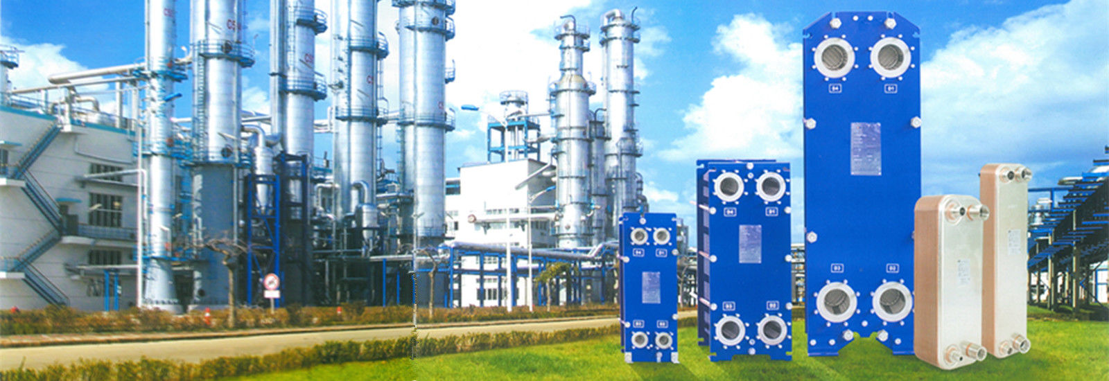
Material: | SUS316L | Max Design Pressure: | 1.6 Mpa |
---|---|---|---|
Connection Mode: | Clamp,Flange,External Thread | Warranty Period: | One Year |
Structure: | Gasket | HS CODE: | 8419500090 |
Application: | Chemical Industry | ||
Highlight: | gasketed plate heat exchanger SUS316L,SUS316L gasketed plate evaporator,Chemical Industry Gasketed Plate Heat Exchanger |
B200H Series Gasket Plate Heat Exchanger SUS316L Material For Chemical Industry
Gasketed plate heat exchangers (GPHEs) are a type of heat exchanger that use a series of plates with gaskets in between to transfer heat between two fluids. Here is some information about gasketed plate heat exchangers:
Working Principle:
GPHEs work on the principle of counter-current flow, where the hot and cold fluids flow in opposite directions. The fluids flow through alternate channels formed by the plates. The heat is transferred from the hot fluid to the cold fluid through the plates, facilitated by the large surface area and turbulent flow created by the corrugated pattern on the plates.
Plate Design:
The plates in a GPHE are typically made of stainless steel, titanium, or other corrosion-resistant materials. They have a corrugated pattern that enhances heat transfer by creating turbulence and increasing the contact between the fluids. The plates are stacked and compressed together with gaskets in between to form a tight seal and maintain separate flow channels for the two fluids.
Gaskets:
Gaskets in GPHEs are made of materials such as Nitrile (NBR), EPDM, or Viton, which provide a flexible and durable seal between the plates. The gaskets prevent mixing of the two fluids and ensure that the fluids flow through their respective channels. Gaskets also help to compensate for any plate misalignment and provide thermal insulation between the plates.
Applications:
GPHEs are used in various industries and applications where efficient heat transfer is required. Some common applications include HVAC systems, industrial processes, refrigeration, food and beverage processing, power generation, marine and offshore systems, and waste heat recovery.
TYPE | A(mm) | B(mm | C(mm | D(mm) | E(mm) | Height ( mm ) ( from middle of bottom to ground )(mm) |
MAX,LC (mm) |
Connector Path (mm) | Max Flow (m3/h) | Design Pressure (Mpa) | Max Pieces |
B30B | N(2.5+X) | 180 | 60 | 480 | 357 | 62 | 500 | 32 | 18 | 1.0 | 95 |
B60B | N2.0+X | 320 | 140 | 920 | 640 | 140 | 1200 | 50 | 36 | 1.6 | 250 |
B60H | N(3.0+X) | 320 | 140 | 920 | 640 | 140 | 1200 | 50 | 36 | 1.6 | 203 |
B100B | N(2.55+X) | 470 | 225 | 1069 | 719 | 183 | 1600 | 100 | 140 | 1.0/1.6/2.5 | 278 |
B100H | N(3.95+X) | 470 | 225 | 1069 | 719 | 200 | 1600 | 100 | 140 | 1.0/1.6/2.5 | 180 |
B150B | N(2.5+X) | 610 | 298 | 1815 | 1294 | 275 | 3000 | 150 | 360 | 1.0/1.6/2.5 | 600 |
B150H | N(3.95+X) | 610 | 298 | 1815 | 1294 | 275 | 3000 | 150 | 360 | 1.0/1.6/2.5 | 600 |
B200H | N(4+X) | 780 | 353 | 2260 | 1478 | 380 | 3000 | 200 | 600 | 1.0/1.6 | 480 |
B250B | N(2.5+X) | 920 | 439 | 2895 | 1939 | 435 | 3000 | 250 | 750 | 1.0/1.6/2.5 | 500 |
B350B | N(3.3+X) | 1150 | 596 | 2882 | 1842 | 470 | 4800 | 350 | 997 | 1.0/1.6 | 700 |
Workshop :
Package :
Test Area :